
OVERVIEW:
A customized autonomous robot with the ability of exact localization in an unknown environment .
In this project , we aim to demonstrate the possibility of using IR wheel encoders and
communicating with Robot Operating System(ROS) for location finding. An autonomous ground
vehicle must be able to locate the exact co-ordinates and navigate to it without having prior
knowledge of the environment . Considering the starting point as reference and navigating through the
path and detecting the final co-ordinates of the mobile robot.
HARDWARE USED:
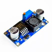
BUCK CONVERTER- LM2596
DC-DC step down voltage converter.
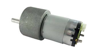
DC GEARED MOTORS2 DC Johnson motors of 100 RPM were used for locomotion.Motor speed is varied using PWM (Pulse Width Modulation)
|
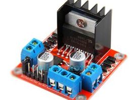
MOTOR DRIVER - L298NUsing this , we can drive 2 DC motors . Basic concept is amplifying low-current control signal.
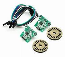
WHEEL ENCODERSThese are used to report back the change in position hence reporting the number of revolutions each wheel has made.
|
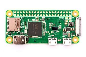
Raspberry pi zero w
This is basically the brain of the bot communicating with motor driver, wheel encoders.
SOFTWARE USED:

VNC VIEWERRemotely accessing raspberry pi zero w.
|

Robot Operating SystemROS is an advanced platform for message passing. It consists
of publishers and subscribers for many to many communication. |
MATHEMATICAL FORMULATION :
Suppose that at sampling interval I the left and right wheel encoders show a pulse increment of NL and NR respectively. Suppose further that
C = π*D/n*Ce
where
C - Conversion factor that translates encoder pulses into linear wheel displacement.
D - Nominal wheel diameter (in mm).
n - Gear ratio of the reduction gear between the motor (where the encoder is attached)
and the drive wheel.
Ce - Encoder resolution (in pulses per revolution).
We can compute the incremental travel distance for the left and right wheel UL,I and UR,I according to :
UL/R,I = CNL/R,I
and the incremental linear displacement of the robot's center-point, J according to
J = ( UL,I + UR,I )/2
Next, we compute the robot's incremental change of orientation
Ø = ( UR,I - UL,I )/b
where b is the wheelbase of the vehicle, ideally measured as the distance between the two contact points between the wheels and the floor.
The robot's new relative orientation Ø I can be computed from
ØI = ØI-1 + Ø
and the relative position of the center-point is
XI = XI -1 + J cosØI
YI = YI-1 + J sinØI
where
XI , YI - relative position of the robot's center-point at instant I.
You can check out our code from this GitHub Repository
For a live demo of our project, you can refer this video:
TEAM MEMBERS:
|
Abhay Khandelwal
|
Ameya Talatule
|
Shreyash Sonawane
|
|
|
|
|
|
